EF-1 Rocket
Mission Objective
Constraint AwarenessProject Briefing
The EF-1 rocket is being developed primarily to experiment with and validate passive roll control, achieved through the addition of carefully canted fins. Its design is a thoughtful optimization, achieving a crucial balance between high performance, affordability, and visual appeal.
- Achieve Level 1 HPR certification
- Safely fly an H-class motor
- Maintain > 2.0 caliber stability
- Validate passive roll control
- Successful parachute deployment at apogee
- Recover without structural damage
Files & Formal Reports
This page briefly covers a summary of the EF-1 rocket. For a detailed breakdown and analysis of the EF-1 rocket design, please refer to the documents below:

Key Design Decisions
Engineering Methodology Cost Awareness Performance Tradeoff Impulse Class AwarenessA detailed analysis and justification of each component is found in the Design Review Report.
Motor Selection
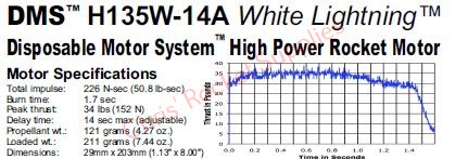
The EF-1 uses an H135W-14A motor, an H-class choice that provides enough thrust to clear our 2,000 foot apogee target while testing the passive roll control system. The I-class motor was ruled out early on as it would have doubled our motor budget without offering a practical performance advantage for this specific mission profile. To fit inside the rocket's narrow airframe and minimize overall mass, a slim, elongated motor configuration was selected.
Airframe Material Trade Study
Conducted a weighted trade study comparing aluminum, cardboard, Blue Tube, and carbon fiber across cost, density, strength, and manufacturability. Blue Tube achieved the highest weighted score due to superior manufacturability and structural adequacy at moderate cost.
| Decision Matrix | ||||||||||||||
|---|---|---|---|---|---|---|---|---|---|---|---|---|---|---|
| Airframe Material | Aluminum [1] | Cardboard [2] | BlueTube [AA] | Carbon Fiber | ||||||||||
| Objective | WF | Parameter | Mag. | Score | Val. | Mag. | Score | Val. | Mag. | Score | Val. | Mag. | Score | Val. |
| Density | 5% | g/cm³ | 2.7 | 2.6 | 0.1 | 0.7 | 10.0 | 0.5 | 1.1 | 6.4 | 0.3 | 1.6 | 4.4 | 0.2 |
| Cost | 10% | USD | 53.8 | 1.9 | 0.2 | 10.3 | 10.0 | 1.0 | 35.7 | 2.9 | 0.3 | 300.0 | 0.3 | 0.0 |
| UTS | 10% | MPa | 90 | 1.8 | 0.2 | 15 | 0.3 | 0.0 | 115 | 2.3 | 0.2 | 500 | 10.0 | 1.0 |
| E | 10% | GPa | 70 | 6.7 | 0.7 | 4 | 0.4 | 0.0 | 10 | 1.0 | 0.1 | 105 | 10.0 | 1.0 |
| M1 | 25% | Rank | 1 | 3.3 | 0.8 | 2 | 6.7 | 1.7 | 3 | 10.0 | 2.5 | 1 | 3.3 | 0.8 |
| M2 | 20% | Rank | 2 | 6.7 | 1.3 | 3 | 10.0 | 2.0 | 3 | 10.0 | 2.0 | 2 | 6.7 | 1.3 |
| M3 | 20% | Rank | 2 | 6.7 | 1.3 | 3 | 10.0 | 2.0 | 3 | 10.0 | 2.0 | 1 | 3.3 | 0.7 |
| Overall value | 4.7 | 7.2 | 7.4 | 5.1 | ||||||||||
Other Materials
All other components are formally justified in the Design Review Report.
Roll Control
Aerodynamics Physics TheoryThe EF-1 incorporates a 2° cant angle on each of its three trapezoidal fins. This slight angular offset generates a small tangential aerodynamic force during ascent, inducing a controlled roll about the vehicle’s longitudinal axis. The resulting spin provides gyroscopic stiffness, helping to average out minor asymmetries in thrust, fin alignment, and aerodynamic loading.
Unlike active control systems, this method adds no mechanical complexity or onboard electronics, instead leveraging aerodynamic principles to improve directional stability. The cant angle was intentionally limited to balance rotational stabilization with minimal additional drag, ensuring that roll enhancement did not significantly reduce apogee performance.
- 2° fin cant
- Induced roll
- Gyroscopic stability
- Tradeoff vs added drag
Manufacturing
Manufacturing CAD Mill Bandsaw 3D PrintingSimulation & Performance
OpenRocketThis analysis was conducted using Open Rocket with intentionally suboptimal conditions to encapsulate realistic launch scenarios. The modified launch conditions were set as follows. An average windspeed of 10 mph at 90° is used.The launch rod was sent to a 7° angle and is 10 feet (120”) long.
Motion vs Time
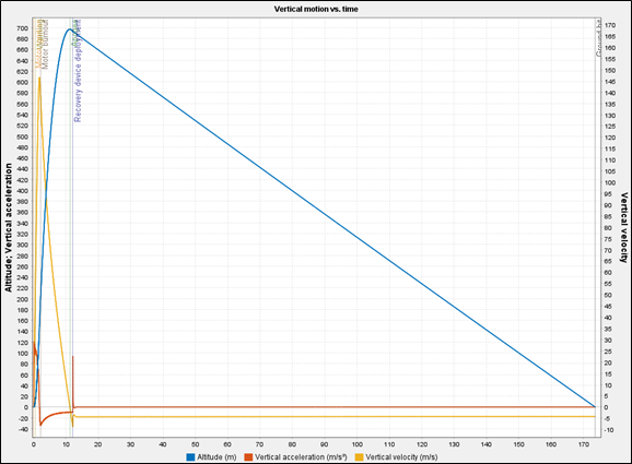
The flight profile shows three distinct phases. During powered flight (0 to 2.07 s), vertical acceleration peaks near 394 ft/s² shortly after liftoff as thrust is highest and propellant mass is still being burned off, then tapers as the motor thrust curve decays toward burnout. Vertical velocity continuously rises during the boost phase as expected with a maximum of 481 ft/s until burnout. As gravity decelerates the rocket during the coasting phase, the vertical velocity decreases until it reaches zero at apogee at 11.21 seconds. After this point, the magnitude of acceleration begins to rise as the rocket enters free fall with a sharp spike indicating the velocity dropped quickly due to the parachute deployment. The vertical acceleration remains at a slower negative value as the rocket slowly descends for 173.7 seconds (Fig. 6). Due to the lightweight nature of EF-1, the rocket achieves an apogee of over 2,200 feet and experiences acceleration within safe bounds. The landing velocity of 18.1 ft/s is slow enough to have no structural damage, but fast enough to not drift too far.
Drift
To verify the parachute was not too wide to allow the rocket to drift too far, the flight trajectory was graphed with altitude against position east of launch. East was selected as that was apart of the initial condition for the direction and speed of the wind. Relative to the launch pad, the rocket lands approximately 1472 feet west. From the launch site, the tree line varies but is not less than 2000 feet, making this magnitude of drift within acceptable bounds for a successful recovery. Theoretically, the rocket is to land within the open field with winds of 10 mph.
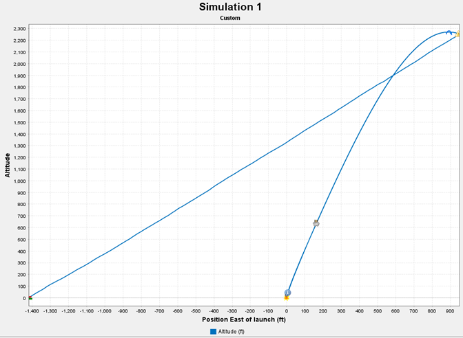
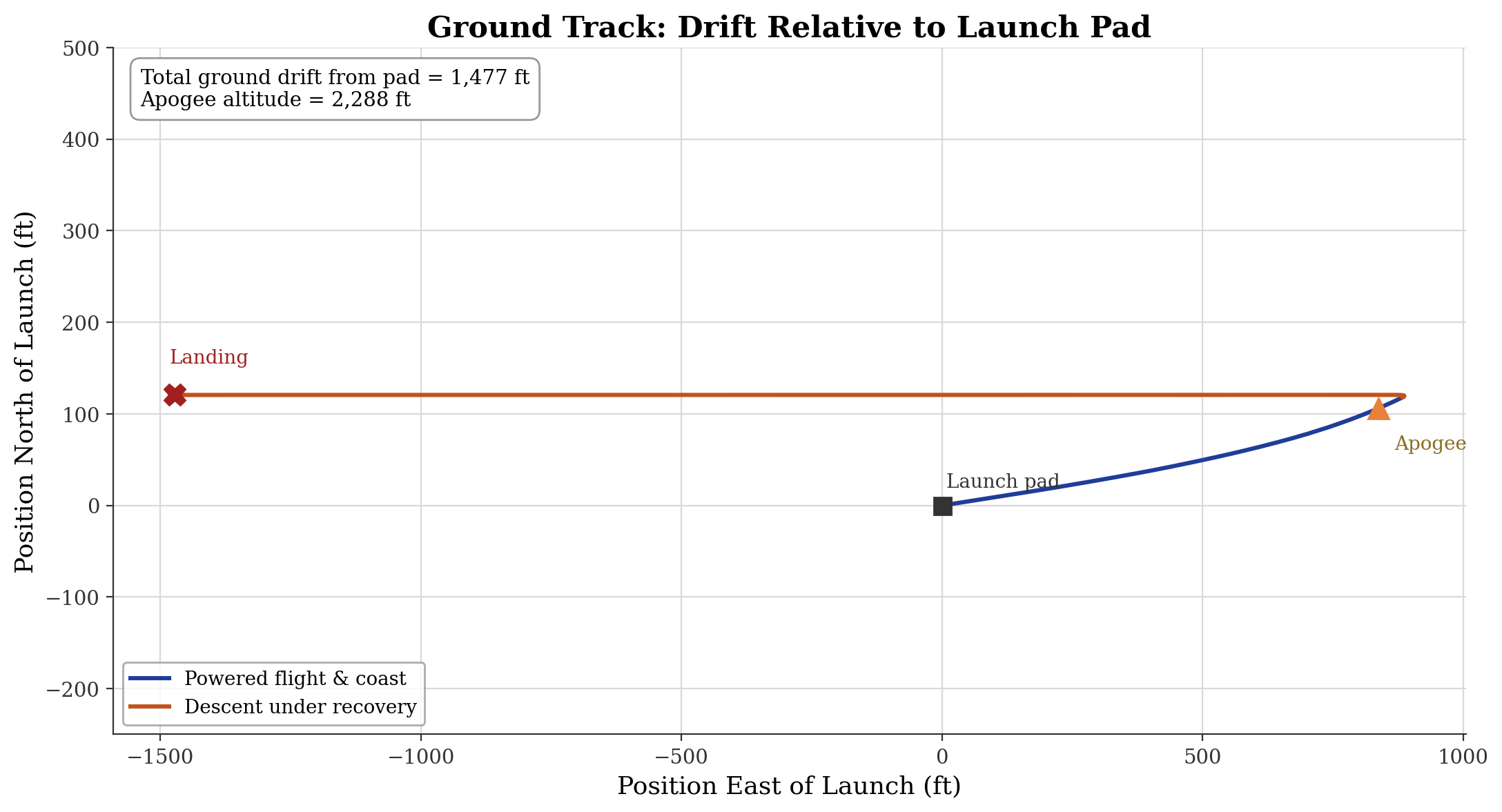
Although the winds in the simulation were westward, making the position east of launch a useful metric for drift, the north-south side is plotted alongside the east-west directions to ensure there is no significant drift in the north-south direction (Fig. 9). Figure 9 also helps visualize the information from Figure 8 but without altitude and from a top-down map view. The rocket only drifts about 100 feet north, verifying the rocket is unlikely to drift out of bounds in the north-south direction or direction perpendicular to the direction of wind.
Stability Analysis
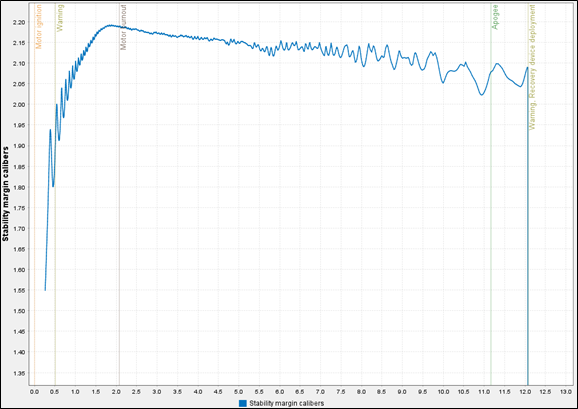
Stability margin is important to maintain aerodynamic stability and ensure a safe flight trajectory. The stability margin should be within 1-2 calibers until the descent stage. Although the stability margin upon ignition is lower at 1.65 calibers, this is still within the 1-2 caliber range. The EF-1 rocket successfully remains around 2 calibers of stability margin for the duration of the flight until descent, passing the rocket in terms of stability analysis for stability margin against time
Thrust & Weight
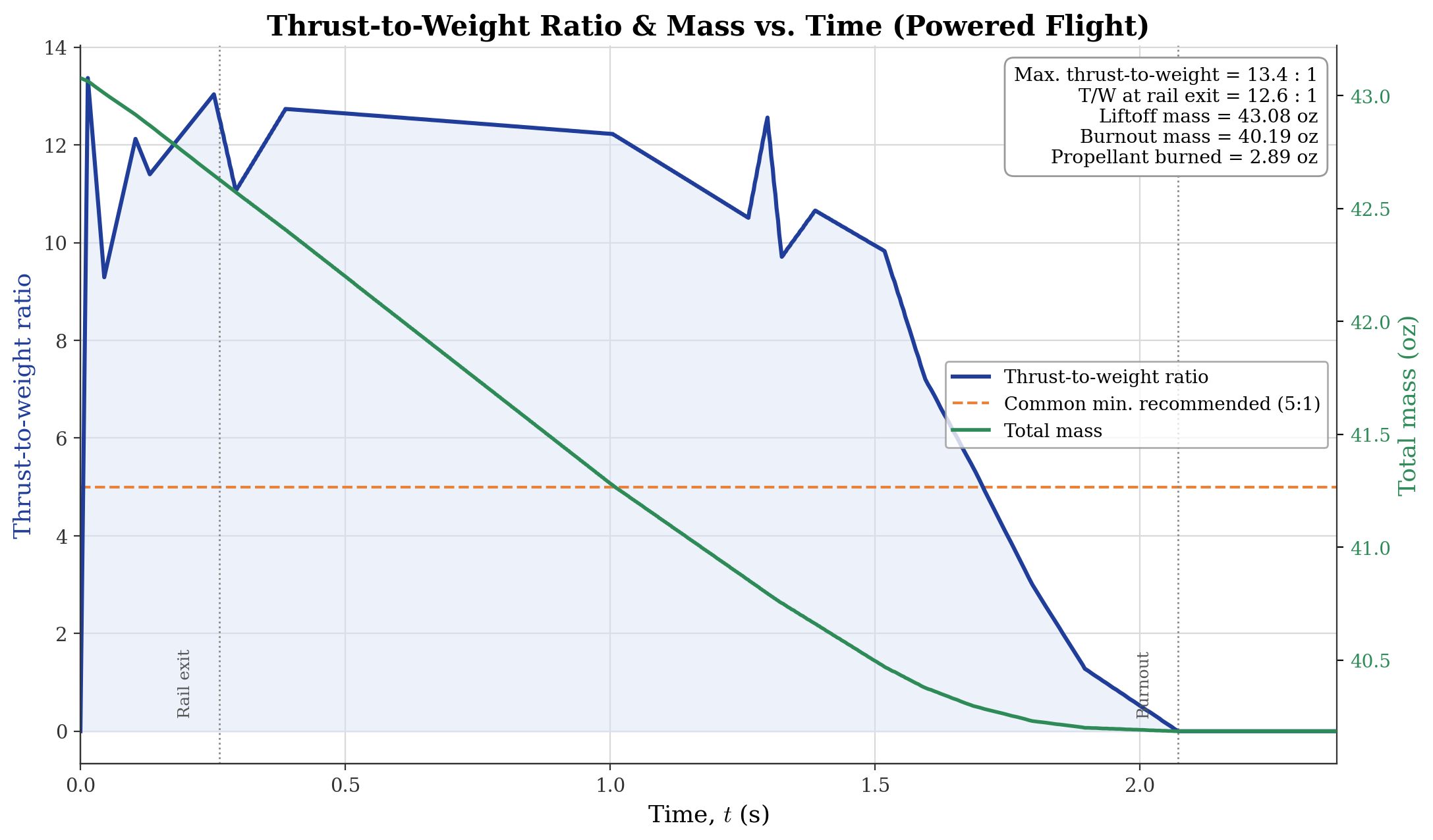
The plot in figure 10 displays the thrust-to-weight ratio and mass against time for the powered flight section. Motor burnout occurs at approximately 2.1 seconds with the mass being completed at burnout out. The thrust to weight ratio spikes to about 13.4:1 in the first fraction of a second (thrust ramps up faster than the rocket has moved), dips as the motor's thrust curve wobbles through its initial peak, climbs back over 12:1 through the early-to-mid burn, then decays steadily as thrust tapers off approaching burnout, hitting zero right at 2.07 s. The jaggedness reflects the motor's actual thrust curve, irregular grain burn, not vehicle behavior. At the rail exit, there is a thrust-to-weight ratio of about 12.6:1 which is well above the common 5:1 rule of thumb, meaning the rocket left the rod at a safe, controllable speed rather than wobbling off with marginal thrust. The total mass falls smoothly and almost linearly from 43.08 oz at liftoff to 40.19 oz at burnout. This continuous curve is smooth due to its cumulative nature. This confirms the use of the HP-H135W motor was an adequate choice.
Flight Results
The rocket achieved stable ascent, clean deployment, and minor cosmetic wear upon landing, satisfying certification criteria.
The following video shows the rocket's ascent: